| MDFS::Info.Comp.Spectrum.Circuits | Search |
| Title | Paper | Size | Description | |
|
Backplane Ctrl2.gif | diagram | 654x973 A4P | 21K | Backplane system for the Spectrum. I prototyped a lot of my hardware with this. |
|
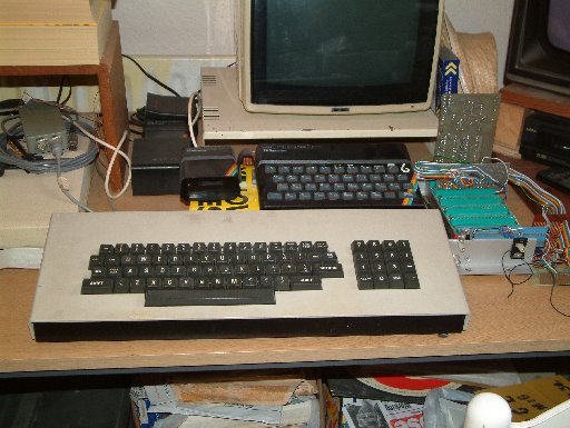
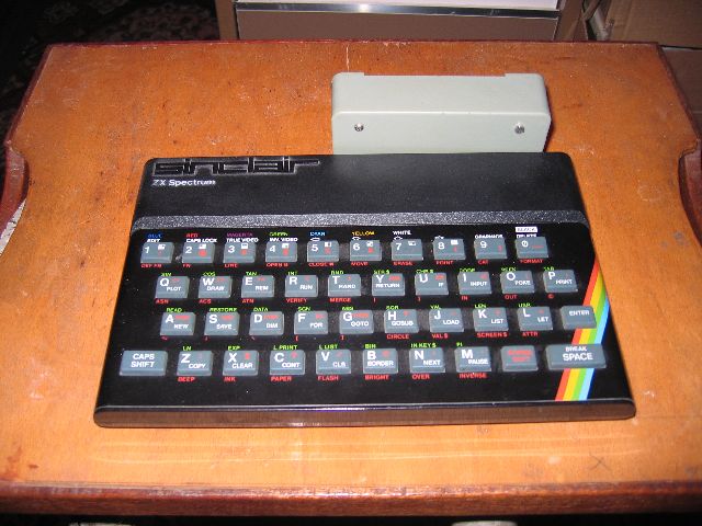
Key+Joy.gif SpecKbd.jpg | diagram picture | 916x1000 A5P | 34K 52K | ASCII keyboard on port &FD/&F9 and Kempston joystick on port &1F. |
| ExtKbd.gif | diagram | 2048x2452 A4L | 104K | Experimental external keyboard interface. |
|
IF1.gif IF1sm.gif IF1th.gif IF1.jpg | diagram diagram diagram picture |
4096x2896 A4L 2048x1448 A5L 720x509 A5L | 176K 68K 13K 7K | Sinclair Interface 1. Initially drawn by hand in 1987, being redrafted. |
|
| diagram | 50K | 2912x2056 A5L | 1-chip Kempston joystick interface. Uses just a single 74LS365 hex buffer, a Spectrum edge connector and a 9D plug. This is the type of joystick interface that causes interupt problems in IM2 as it only decodes ~IORQ and A5, so any I/O access with A5=0 reads the joystick. So, an interupt acknowledge with ~IORQ=0, but ~RD=1 and ~WR=1 accesses the joystick. |
|
| diagram | 50K | 2912x2064 A5L | 2-chip Kempston joystick interface. Uses just a single 74LS365 hex buffer, a single 74LS32 quad-OR, a Spectrum edge connector and a 9D plug. This is the type of joystick interface fully decodes IN 31, so does not interfere with interupts in IM2. The addition of a 35p multiple OR gate decodes ~IORQ, ~RD, A7, A6 and A5 to correctly respond to IN 31. |
|
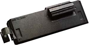
ROM1.gif ROM1t.gif ROMBox.jpg ROMBox2.jpg | diagram diagram picture picture | 127K 28K 79K 54K |
2912x4096 A4P 264x512 A5P |
Single socket external ROM box. Can plug in an 16K or 32K ROM.
ROMs selected with OUT &FD,&nn. b4=0 - external ROM, b4=1 - internal ROM. b6=0 - lower 16K, b6=1 - upper 16K. Gives: |
| ROM4.gif | diagram | 185K | 2912x4096 A5P |
Four-socket external ROM box. Can plug in a combination
of 16K and 32K ROMs. ROMs selected with OUT &FD,&nn. b4=0 - external ROM, b4=1 - internal ROM. b6-b7=external ROM number Gives: |